Socket Weld Take Off Chart
In the world of pipefitting and plumbing, precision is everything. A small miscalculation can lead to costly leaks, structural failures, and safety hazards. That’s where a socket weld take-off chart comes into play—a critical tool that ensures every pipe and fitting aligns perfectly before welding. Whether you’re a seasoned pipefitter, an engineer, or a DIY enthusiast working on piping systems, understanding how to use a socket weld take-off chart is essential for efficiency and reliability. This guide will walk you through the basics, from defining what a socket weld joint is to mastering the calculations that keep your projects leak-free and structurally sound.
Understanding the Purpose of a Socket Weld Take Off Chart
What is a Socket Weld Joint?
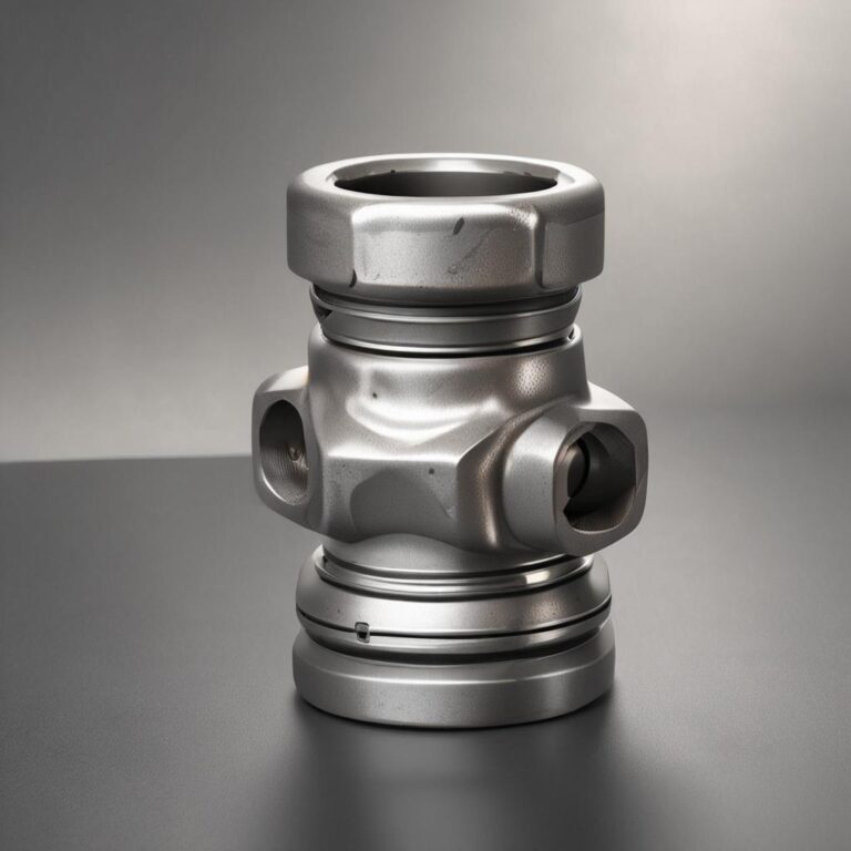
A socket weld joint connects pipes by inserting the pipe end into a recessed socket of a fitting (like a coupling, elbow, or tee) before welding. Unlike butt welding, which joins pipes end-to-end, or threaded connections, which rely on screw threads, socket welds create a strong, sealed connection ideal for high-pressure applications. The recessed socket allows for slight misalignment during assembly, making it a go-to choice in industries like oil and gas, chemical processing, and HVAC.
Why Take-offs Are Critical
Accurate take-offs—measurements that determine the required pipe lengths and fitting dimensions—are vital for several reasons. They ensure proper alignment, prevent leaks, and maintain the integrity of the piping system. Without precise take-offs, you risk weak joints, misaligned pipes, or even catastrophic failures, especially in high-pressure environments.
Industries That Rely on Socket Weld Charts
Socket weld take-off charts are indispensable in industries where reliability is non-negotiable. These include:
- Oil and gas pipelines
Key Components of a Socket Weld Take Off Chart
Dimensions and Measurements
A socket weld take-off chart provides pre-calculated values for pipe sizes (NPS), schedules (wall thickness), and socket depth allowances. For example, a 2-inch Schedule 40 pipe will have a different take-off length than a 2-inch Schedule 80 pipe due to variations in wall thickness. The chart accounts for these differences to ensure a snug fit without excessive welding.
Angles and Offsets
When working with elbows or tees, angles and offsets become crucial. A 90° elbow, for instance, requires precise calculations to maintain the correct flow path. The chart includes formulas (like the Pythagorean theorem for offsets) to help pipefitters adjust for these angles without trial-and-error.
Formulas and Standards
Socket weld take-off charts follow industry standards like ASME B31.1 (Power Piping) and ASME B16.11 (Forged Fittings). These standards dictate socket depths, tolerances, and other critical measurements, ensuring consistency across projects.
How to Use a Socket Weld Take Off Chart
Step-by-Step Guide
Using a socket weld take-off chart is straightforward once you understand the basics:

- Measure the pipe and fittings: Identify the NPS, schedule, and fitting type (e.g., elbow, tee).
- Locate the correct values on the chart: Cross-reference your measurements with the chart’s pre-calculated take-off lengths.
- Adjust for fittings and angles: Use the chart to account for offsets or branching connections.
For example, if you’re installing a 1-inch Schedule 80 pipe with a 90° elbow, the chart will provide the exact take-off length needed to ensure a proper fit.
Tools Required for Accurate Take-offs
To use a socket weld take-off chart effectively, you’ll need:
Key Metrics
Performance metrics for Socket Weld Take Off Chart

- Measuring tape or ruler
Common Mistakes to Avoid
Even experienced professionals can make errors. Here’s what to watch out for:
- Misreading the chart (e.g., confusing Schedule 40 with Schedule 80).
Types of Socket Weld Take Off Charts
Standard vs. Custom Charts
Most projects use pre-printed standard charts covering common NPS and schedules. However, custom charts may be necessary for non-standard angles or unique fitting configurations.
Material-Specific Charts
Different materials (stainless steel, carbon steel, alloys) have unique properties affecting take-off calculations. A chart designed for stainless steel, for example, may account for its higher thermal expansion.
Digital vs. Printed Charts
Traditional printed charts are reliable, but digital tools—such as mobile apps or CAD software—offer dynamic calculations and real-time adjustments, making them ideal for complex projects.
Factors to Consider When Selecting a Socket Weld Take Off Chart
Pipe Size and Schedule Compatibility
Ensure the chart matches your pipe’s NPS and schedule. A mismatch can lead to misalignment or leaks.
Fitting Type and Configuration
Different fittings (elbows, tees, reducers) have unique take-off values. Verify the chart includes your specific fitting type.
Project Complexity
For simple systems, a standard chart suffices. Complex layouts may require advanced software or custom charts.
Compliance with Codes and Standards
Always choose a chart that aligns with relevant codes (e.g., ASME B31.3 for process piping). Compliance is critical for safety and regulatory approvals.
Real-World Example: Using a Socket Weld Take Off Chart in a Project
Scenario Setup
Imagine designing a 2-inch NPS, Schedule 40 piping system with 90° elbows. You need branch lines connecting to a main header. The chart will help determine the exact take-off lengths for each connection.
Walkthrough of Calculations
Step 1: Measure the pipe (2-inch NPS, Schedule 40).
Step 2: Locate the socket depth allowance for the 90° elbow on the chart.
Step 3: Adjust the take-off length by subtracting the socket depth from the total pipe length.
Result: A precise, leak-free connection every time.
Visual Aids
Including diagrams or screenshots of the chart in action can make the process clearer. For example, a labeled diagram showing the take-off points for a tee fitting would reinforce the calculations.
Conclusion
A socket weld take-off chart is an indispensable tool for anyone working with piping systems. By ensuring accurate measurements and proper alignment, it prevents leaks, reduces waste, and enhances system reliability. Whether you’re a seasoned professional or a DIYer, mastering these charts will save you time, money, and headaches. Always verify your charts against project specifications, stay updated on industry standards, and prioritize precision—because in pipefitting, every millimeter matters.
FAQ Section
1. What is the difference between socket weld and butt weld take-off charts?
Socket weld charts account for the insertion depth of pipes into fittings, while butt weld charts focus on bevel angles and root gaps for end-to-end welding.
2. How do I read a socket weld take-off chart accurately?
Match your pipe’s NPS, schedule, and fitting type to the correct values on the chart. Double-check measurements to avoid errors.
3. Can socket weld take-off charts be used for all pipe materials?
Generally, yes, but material-specific charts are recommended for materials with unique properties (e.g., stainless steel’s thermal expansion).
4. What tools do I need to create a socket weld take off?
Essential tools include a measuring tape, protractor, calculator, and possibly CAD software for complex systems.
5. Are there industry-specific variations in socket weld take-off charts?
Yes. For example, ASME B31.3 (process piping) and ASME B31.1 (power piping) have slight differences in tolerances and socket depths.