Universal Joint Socket Drawing
Universal joints are crucial components in mechanical systems, enabling the transmission of rotational motion between misaligned shafts. Whether in automotive drivetrains, industrial machinery, or heavy equipment, these flexible couplings rely on precise socket designs to function efficiently. A well-drafted universal joint socket drawing is essential for ensuring compatibility, durability, and optimal performance. This guide provides engineers, designers, and manufacturers with the knowledge needed to create accurate and functional socket drawings, covering everything from key dimensions to industry standards.
Understanding Universal Joints
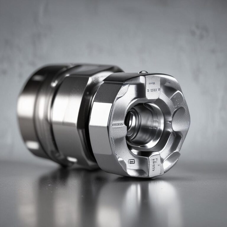
Universal joints, often referred to as U-joints, are mechanical devices that transmit torque between two rotating shafts that are not in a straight line. Their ability to accommodate angular misalignment makes them indispensable in various applications. The two most common types are the Cardan joint and the Constant Velocity (CV) joint, each suited for different motion requirements.
Where Universal Joint Sockets Are Used
-
Industrial Machinery: Used in conveyor systems, pumps, and generators where shaft alignment is challenging.
Automotive Applications: Essential in drivetrains, steering systems, and transmission systems.
Heavy-Duty Equipment: Found in mining, construction, and agricultural machinery for reliable power transmission.
Key Elements of a Universal Joint Socket Drawing
A precise socket drawing ensures proper manufacturing and assembly. The following elements are critical for accuracy.
Dimensions and Specifications
-
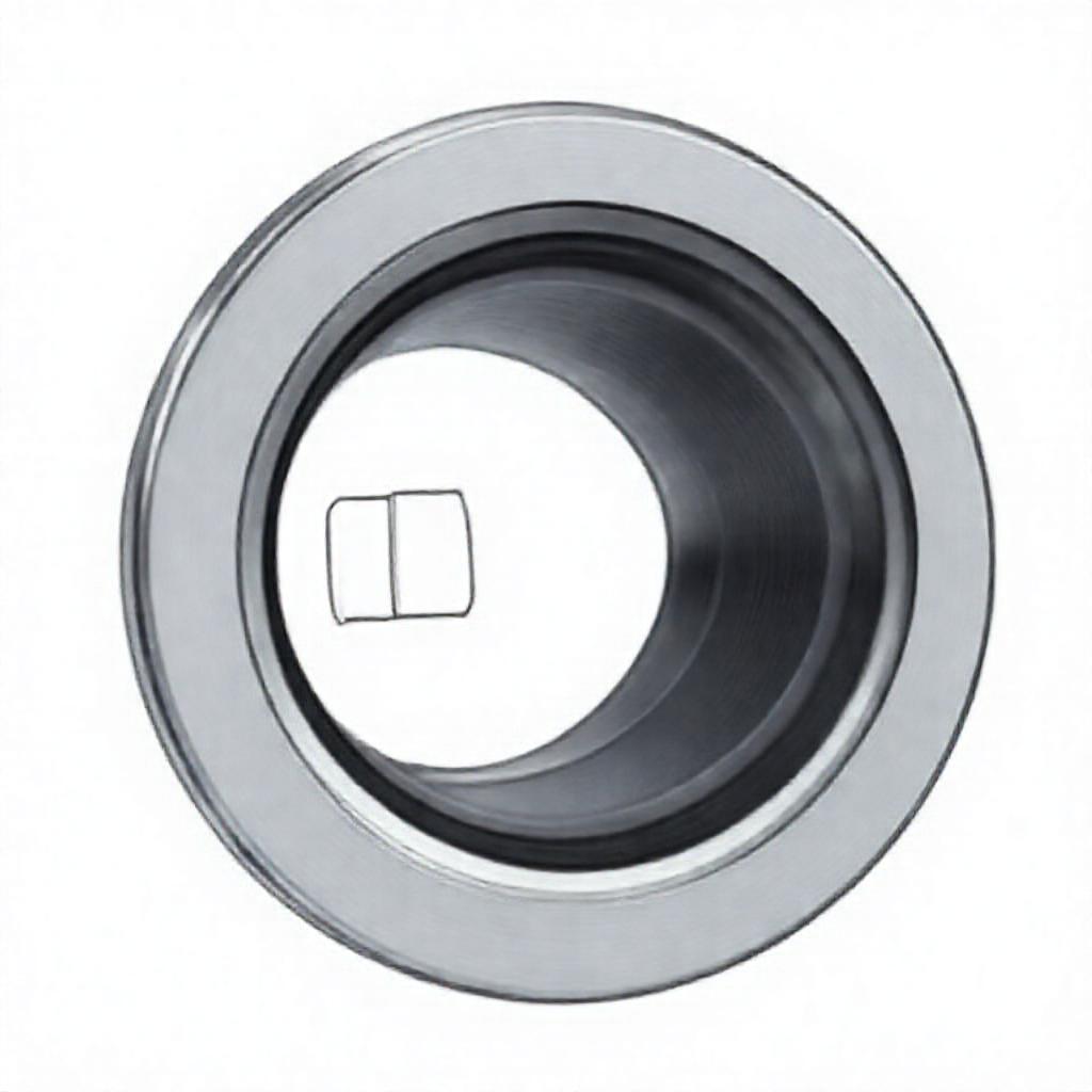
Bore Diameter: Determines shaft compatibility and load-bearing capacity.
Width and Height: Affect overall joint dimensions and fit within assemblies.
Tolerances: Must be clearly defined to prevent misalignment or premature wear.
Geometric Features
-
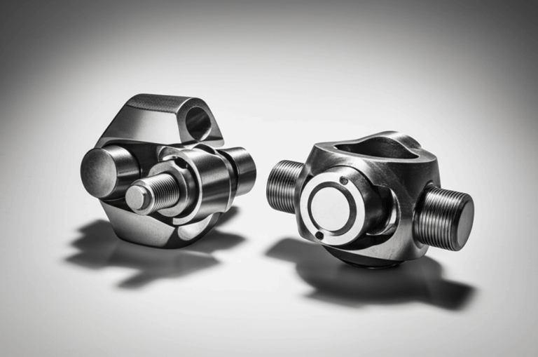
Splines and Threads: Ensure secure connection to the cross or bearing assembly.
Keyways: Provide additional locking mechanisms for high-torque applications.
Angular Tolerances: Critical for smooth motion and reducing stress concentration.
Cross-Sectional Views
-
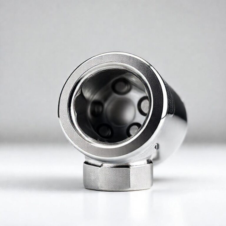
Critical Sections: Highlight internal features like needle bearings or lubrication channels.
Hidden Lines: Indicate internal components not visible in standard views.
Centerlines: Ensure proper alignment during manufacturing and assembly.
Best Practices for Creating Accurate Socket Drawings
To ensure manufacturing precision, follow these best practices when creating socket drawings.
Software and Tools
-
CAD Software: AutoCAD for 2D drafting, SolidWorks for 3D modeling, and Fusion 360 for collaborative design.

2D vs. 3D: Use 2D for detailed dimensions and 3D for visualizing complex geometries.
Ensuring Manufacturing Precision
-
GD&T Principles: Apply geometric dimensioning and tolerancing to specify critical features.
Common Mistakes: Avoid oversimplifying tolerances or neglecting wear considerations.
Universal Joint Socket Drawing Standards
Adhering to industry standards ensures compatibility and reliability across applications.
Industry Standards (ISO, ANSI, DIN, etc.)
-
ISO 14523: Covers general specifications for universal joints.
ANSI B94.6: Provides guidelines for industrial U-joints.
DIN 808: Used in European automotive and machinery industries.
Custom vs. Standardized Drawings
Comparison table for Custom vs. Standardized Drawings
-
Custom Designs: Needed for specialized applications or unique load requirements.
Standardized Drawings: Ensure interchangeability and simplify procurement.
Common Challenges in Universal Joint Socket Design
Designing an effective socket requires addressing potential issues to enhance performance and longevity.
Misalignment and Wear Issues
-
Socket Design Impact: Poorly designed sockets can increase wear on bearings and cross assemblies.
Solution: Use angular tolerances and robust materials to minimize misalignment.
Material Selection and Durability
-
High-Load Applications: Chrome-alloy steels or high-strength alloys are ideal.
Corrosion Resistance: Consider coatings or stainless steel for harsh environments.
Assembly and Maintenance Considerations
-
Disassembly Ease: Design sockets with accessible fasteners for maintenance.
Lubrication Points: Include grease fittings for long-term joint health.
Conclusion
Creating accurate universal joint socket drawings is vital for ensuring mechanical efficiency and reliability. By understanding key dimensions, adhering to industry standards, and following best practices, engineers can design sockets that meet performance demands. Whether for automotive, industrial, or heavy-duty applications, precision in socket design directly impacts the success of mechanical systems.
FAQ: Universal Joint Socket Drawing
Q1: What is the most critical dimension in a universal joint socket drawing?
The bore diameter is the most critical dimension, as it must match the shaft size precisely to ensure a secure fit and proper torque transmission. Spline fit tolerances are also crucial to prevent misalignment.
Q2: Can I use a standard template for universal joint socket drawings?
Standard templates work for common applications, but customization is necessary for unique load requirements or non-standard shaft sizes. Always verify fit and performance before finalizing a design.
Q3: How do I ensure my socket drawing meets industry standards?
Reference key standards like ISO 14523, ANSI B94.6, or DIN 808 to ensure compliance. Consulting industry guidelines and using standardized dimensions will help meet regulatory requirements.
Q4: What software is best for creating universal joint socket drawings?
AutoCAD is ideal for 2D technical drawings, while SolidWorks offers robust 3D modeling capabilities. Fusion 360 is a versatile option for collaborative design and simulation.
Q5: How do I account for wear and misalignment in socket design?
Use angular tolerances to reduce stress, select durable materials, and include lubrication points to minimize wear. Regular maintenance checks can also extend the joint’s lifespan.